SPH-DEM Examples
Poiseuille Flow
The Poiseuille flow is used to build the tutorial of the SPH-DEM coupling. This laminar flow is able to show that the velocity profile and the tangential force given on the walls correspond to the results produced by the analytical expressions. The whole simulation is described in the following code, which will be explained in detail:
                                // MechSys
                                #include <mechsys/sph/Domain.h>
                                #include <iostream>
                                #include <fstream>

                                using std::cout;
                                using std::endl;

                                int main(int argc, char **argv) try
                                {

                                    size_t Nproc = omp_get_max_threads();

                                    if (argc>1) Nproc = atoi(argv[1]);

                                    SPH::Domain     dom;
                                    dom.Nproc       = Nproc;
                                    dom.Dimension   = 2;
                                    dom.Scheme      = 1;
                                    dom.Gravity     = 1.e-4,0.0,0.0;
                                    dom.KernelType  = 0;
                                    dom.GradientType= 0;
                                    dom.VisEq       = 0;
                                    dom.BC.Periodic[0] = true;

                                    dom.XSPH        = 0.5;
                                    dom.DeltaSPH    = 0.15;

                                    //Simulation time
                                    double Tf       = 200.0;
                                    int numfiles    = 200;
                                    double dtoutput = Tf/numfiles;

                                    //size of domain and parameters
                                    double H    = 0.1;
                                    double L    = H;
                                    int    n    = 60;
                                    double dx   = H/n;
                                    double h    = dx*1.3;
                                    dom.InitialDist = dx;


                                    double rho      = 1000.0;
                                    double Mu       = 1.0e-1;
                                    double Cs       = 0.07;
                                    double P0       = 0.0;
                                    double CFL      = 0.1;
                                    double timestep = (CFL*h/(Cs));
                                    double Re       = (rho*H*1.23e-3)/Mu;

                                    //////////////////////////////////////// DECLARING SPH PARTICLES ///////////////////////////////////////

                                    dom.AddBoxLength(/*Tag*/1, /*Position*/Vec3_t (0.0,  0.0, 0.0), /*Length*/L, /*Height*/H, /*Width*/0.0, /*Radius*/dx/2.0, /*Density*/rho, /*Smoothing*/h, /*Packing*/1, /*Rotation*/0, /*Random*/false, /*Fixed*/false);

                                    for (size_t i=0; i <dom.Particles.Size(); i++){
                                        dom.Particles[i]->Material    = 1;
                                        dom.Particles[i]->Constitutive= 11;
                                        dom.Particles[i]->Mu          = Mu;
                                        dom.Particles[i]->PresEq      = 0;
                                        dom.Particles[i]->P0          = P0;
                                        dom.Particles[i]->Cs          = Cs;
                                        dom.Particles[i]->Alpha       = 0.05;
                                        dom.Particles[i]->Beta        = 0.05;
                                        dom.Particles[i]->TI          = 0.3;
                                        dom.Particles[i]->TIn         = 4.0;
                                        dom.Particles[i]->TIInitDist  = dx;
                                        dom.Particles[i]->Shepard     = true;
                                    }

                                    //////////////////////////////////////// DEM BOUNDARY CONDITIONS ///////////////////////////////////////
                                    dom.AddSegment(/*Tag*/ -2,/*PositionL*/ Vec3_t(-0.1*L,H,0.0),/*PositionR*/Vec3_t(1.1*L,H,0.0),/*Thickness*/dx,/*Density*/rho);
                                    dom.AddSegment(/*Tag*/ -1,/*PositionA*/ Vec3_t(-0.1*L,0.0,0.0),/*PositionB*/Vec3_t(1.1*L,0.0,0.0),/*Thickness*/dx,/*Density*/rho);

                                    for (size_t j = 0;j<dom.DEMParticles.Size();j++){
                                        dom.DEMParticles[j]->FixVeloc();
                                        dom.DEMParticles[j]->Props.Mu  = 0.0;
                                        dom.DEMParticles[j]->Props.eps = 0.0;
                                        for (size_t i=0; i<dom.Particles.Size(); i++){
                                            double dist = DEM::Distance(dom.Particles[i]->x,*dom.DEMParticles[j]->Faces[0]);
                                            if (dist<dom.DEMParticles[j]->Props.eps || dom.DEMParticles[j]->Props.eps == 0.0) dom.DEMParticles[j]->Props.eps = dist;
                                        }
                                    }

                                    cout << "Cs = " << Cs << endl;
                                    cout << "h  = " << h  << endl;
                                    cout << "dx = " << dx << endl;
                                    cout << "Re = " << Re << endl;

                                    ////////////////////////////////////////// SOLVING THE SYSTEM //////////////////////////////////////////
                                    dom.Solve(/*tf*/Tf,/*dt*/timestep,/*dtOut*/dtoutput,"test06",numfiles);
                                    return 0;
                                }
                                MECHSYS_CATCH
Initialisation
MechSys/SPH-DEM simulations are prepared with a C++ source code. The first step is to include the required MechSys libraries. In this case, the file domain.h contains the SPH domain definitions:
#include <mechsys/sph/domain.h>
Simulation script structure
The simulation script structure is:
                                    #include ...
                                    int main(int argc, char **argv) try
                                    {
                                        ...
                                    }
                                    MECHSYS_CATCH
After including the required MechSys' libraries (and C++ standard libraries, if necessary), the main
function is declared.
For MechSys, it is essential to add the try keyword just after
the int main() and before the first opening brace {. Then, after the last closing
brace, the MECHSYS_CATCH is added.
Declaring the SPH Domain
The following line returns an upper bound on the number of threads that could be used:
size_t Nproc = omp_get_max_threads();
If the first argument is introduced by following the execution command, the number of threads will be reassigned:
if (argc>1) Nproc = atoi(argv[1]);
The line,
SPH::Domain dom;
declares the container dom of the class SPH::Domain. This class defines the SPH universe and has some functions to include SPH particles and DEM particles, some of which will be used in this tutorial.
The SPH model has many options to solve the equations. Thus, once the domain is named (e.g., dom), the functions and their options are selected using such an extension. For instance, the dimensionality of the problem can be selected using an integer, 2 or 3:
dom.Dimension = 2;
There are two explicit schemes to solve the temporal derivatives:
- 0 → Modified Verlet (Ghadimi, 2012)
- 1 → Leapfrog (Braune & Lewiner, 2013)
And it can be called as follows:
dom.Scheme = 1;
The gravity is a vector defined in the domain, which directions
are x, y and z.
dom.Gravity = 1.e-4,0.0,0.0;
Many kernel functions can be found in the literature. Mechsys has three options (Korzani et al., 2017):
- 0 → Cubic kernel
- 1 → Quintic
- 2 → Quintic Spline
dom.KernelType = 0;
Remark: The option called Quintic is known as Wendland C2 or Wendland Quintic kernel function. Wendland kernel avoids pairing (or clumping) instability that occurs where there are more neighbouring SPH particles in the influence domain that a kernel function can accommodate (Dehnen & Aly, 2012; Bui & Nguyen, 2020).
Two options are available to discretise the gradient of the pressure or the stress tensor depending on the form of the density as a denominator (Monaghan, 2005):
- 0 → Squared density
- 1 → Multiplied density
dom.GradientType = 0;
If the system to be solved is a Newtonian fluid, there are four options to discretise the second order derivative term:
- 0 → Morris et al. (1997).
- 1 → Shao & Lo (2003).
- 2 → Real viscosity for incompressible fluids.
- 3 → Real viscosity for compressible fluids (Takeda et al., 1994).
Then, it can be chosen as:
dom.VisEq = 0;
In this case, periodic boundary conditions are used. To indicate the direction in which the periodic BC will be activated (x=0, y=1 and z=2) an integer is assigned as shown in the following command:
dom.BC.Periodic[0] = true;
Thus, option 0 is indicating that the periodic BC is on the x-direction.
Also, it is possible to use some correction expressions to improve the solution given by SPH. XSPH is a widely implemented term to correct the position of the particles. This can be activated by calling the following function and assigning a value between 0 and 1. A typical value is 0.5:
dom.XSPH = 0.5;
The basic SPH structure produces a checkerboard pattern so that a filter to smooth the pressure field is necessary. Thus, Delta-SPH is a diffusive term added in the mass conservation equation that can be activated by calling the following function and assigning a value between 0 and 1, depending on the case.
dom.DeltaSPH = 0.15;
Then Tf defines the final time of the simulation, numfiles the number of frames to produce for visualization and analysis and dtoutput defines the time-step to print the files, but it is not related to the real time-step and stability condition.
                                    double Tf       = 200.0;
                                    int numfiles    = 200;
                                    double dtoutput = Tf/numfiles;
Some parameters are defined to set up the size of the problem. Thus, height H and length L of a box that will contain the SPH particles are defined. Also, the number of particles n and the spacing among them dx is defined as well as the smoothing length double h = dx*1.3.
                                    double H    = 0.1;
                                    double L    = H;
                                    int    n    = 60;
                                    double dx   = H/n;
                                    double h    = dx*1.3;
The value 1.3 is a scaling factor of the spread of the smoothing function, and it can be from 0.6 to 2.0; however, values between 1.1 and 1.3 are highly recommended. Also, it is necessary to assign the distance between points using the following function:
dom.InitialDist = dx;
Then, some of the variables or parameters that can influence the time-step and the stability are defined. Density rho, dynamic viscosity Mu, speed of the sound Cs, a background pressure P0, and the stability condition directly CFL :
                                    double rho  = 1000.0;
                                    double Mu   = 1.0e-1;
                                    double Cs   = 0.07;
                                    double P0   = 0.0;
                                    double CFL  = 0.1;
                                    double timestep = (CFL*h/(Cs));
The time-step is defined as a function of the CFL that typically involves choosing a value lower than 0.1. The commonly chosen sound speed for simulations differs from the physical value to make the solution terminable without affecting the results; otherwise, the simulation may take too much computation time. Morris (1997) shows some definitions regarding the speed of the sound and stability condition. On the other hand, Poiseuille case requires that the regime of the flow be laminar; thus, it is verified by the Reynolds number as follows:
double Re = (rho*H*1.23e-3)/Mu;
Declaring the SPH Particles
A function that will introduce the SPH particles as an array into the domain is called. Three functions can be used for such a purpose; however, AddBoxLength is implemented in this example. Such a function requires some inputs:
dom.AddBoxLength(/*Tag*/1, /*Position*/Vec3_t (0.0, 0.0, 0.0), /*Length*/L, /*Height*/H, /*Width*/0.0, /*Radius*/dx/2.0, /*Density*/rho, /*Smoothing*/h, /*Packing*/1, /*Rotation*/0, /*Random*/false, /*Fixed*/false);
The first parameter is a "Tag" to distinguish different subgroups of particles. The vector Vec3_t(0.0, 0.0, 0.0) indicates the origin of the box with the SPH particles, which coordinates can be seen as Vec3_t(Left, Bottom, Front). Then, "Length", "Height", and "Width" must be defined by double type numbers. The "Radius" is typically defined as dx/2. Then, two parameters are called "Density" and "smoothing length" which were defined above. "Packing": this option gets an integer value to define particles packing arrangement. "Rotation": this option gets an integer value to define the direction in Hexagonal Close Packing. "Random": it is a boolean variable to add randomness in the position of each particle proportional to its radius. "Fixed": it is a boolean variable for defining if the particle is fixed or free, which is useful for boundary conditions.
Remark: rectangle and cube are the primary shapes discretised by the SPH points, in 2D and 3D, respectively. Then, the rectangle and cube can be reshaped by deleting some particles placed in unwanted zones using basic functions. For example, the equation of the straight line, plane, circle, sphere, etc. It can be done by changing the initial tag of the particles through the variable called dom.Particles[i]->ID = .... Then, the particles with that new ID can be eliminated using a command from the code called dom.DelParticles(ID). A clear example of this procedure can be found in a case called "test08.cpp" content into the folder "tsph" from Mechsys.
After calling the function to create the SPH points, it is necessary to assign the parameters to each particle that define the type and behaviour of the simulated material. This will be done by using a loop for, which structure is written as:
                                    for (size_t i=0; i <dom.Particles.Size(); i++){
                                         ...
                                    }
It is necessary to use the following structure to assign or define certain properties: dom.Particles[i]->parameter = value. Thus, the first parameter refers to the type of material, where there are three options that can be selected by an integer:
- 1 → Fluid
- 2 → Solid
- 3 → Soil
dom.Particles[a]->Material = 1;
There are also some options to choose the constitutive model. There are five options for fluids, one for solids and two for soils:
- 11 → Linear (Newton, 1687).
- 12 → Bingham regularised (Papanastasiou, 1987).
- 13 → Bingham-Bilinear (Imran et al., 2001).
- 14 → Cross model (Shao & Lo 2003).
- 15 → Herschel-Bulkley (Ké & Turcotte, 1980).
- 2 → Elastic Perfect-Plastic with Von-Mises failure criteria.
- 31 → Elastic Perfect-Plastic with Drucker-Praguer failure criteria (Bui et al., 2008).
- 32 → Hypoplastic model (Peng et al., 2015).
Then, the selection is made by the following command:
dom.Particles[a]->Constitutive = 11;
Once the constitutive model for fluid is chosen, some parameters must be modified by a double value, the dynamic viscosity Mu for the Newtonian fluid. When the fluid is non-Newtonian, other parameters must be modified, such as reference dynamic viscosity MuRef and the yield stress T0, which are used in all the non-Newtonian fluid models. The regularisation parameter m used in Bingham and Herschel-Bulkley models, which value is 300.0 by default; and time parameter t0mu used in Herschel-Bulkley. Thus, following the syntaxis here used, the parameter can be modified depending on the selected model as shown below:
                                    dom.Particles[a]->Mu          = 1.0e-3;
                                    dom.Particles[a]->MuRef       = 2.0;
                                    dom.Particles[a]->T0          = 5.0;
                                    dom.Particles[a]->m           = 500.0;
                                    dom.Particles[a]->t0mu        = 5.0e-4;
Such values depend on the experimental measurement. For further details regarding the models, review the papers cited above.
Since the system is assumed to be weakly compressible, an equation of state (EOS) must be used, and three options are given.
- 0 → Nearly incompressible fluids (Cole, 1965, p. 38-44).
- 1 → Artificial EOS (Morris et al., 2000).
- 2 → (Morris et al., 1997).
Thus, the EOS is selected as:
dom.Particles[a]->PresEq = 0;
Also, EOS 0 and 1 has a background pressure that is 0.0 by default, and can be modified using the following command:
dom.Particles[a]->P0 = P0;
The speed of the sound has an essential role since it influences the stability of the solution and the CPU time. Although a value is assigned in this example, some expressions can be found in the literature to compute the initial Cs, as shown in Morris et al., (1997). Typically, the value used is not the physical one. This is done to obtain results in a reasonable computational time, ensuring that it will not affect the quality of the solution.
dom.Particles[a]->Cs = Cs;
In order to diminish excessive oscillations caused by the shock fronts, an artificial viscous term is introduced. The filter can be used by the following commands:
                                    dom.Particles[a]->Alpha       = 0.1;
                                    dom.Particles[a]->Beta        = 0.1;
Alpha and Beta are real numbers whose values depend on the material and case. Their value can be between 0.0 and 1.0. To activate this viscosity, either Alpha or Beta should be greater than zero. It has been found that 1.0 is an appropriate value for Alpha and Beta when simulating soils and close to 0.05 for fluid simulations.
SPH particles are prone to agglomerate in an unphysical way when particles have negative pressure coming from the equation of state. Monaghan (2000) introduce a term in the momentum equation to mitigate such a problem (known as tensile instability in the literature), which works as an artificial pressure to give repulsion between particles. It can be implemented in code using the following lines:
                                    dom.Particles[a]->TI          = 0.3;
                                    dom.Particles[a]->TIn         = 4.0;
                                    dom.Particles[a]->TIInitDist  = dx;
By default, TIn is 4.0 in the code as recommended by Gray et al. (2001) for solid materials. To activate this option in the code, TI should be greater than zero. Generally, TI and TIn are recommended to be 0.3 and 4.0 for solids and fluids (Gray et al., 2001; Monaghan 2000), 0.5 and 2.55 for soils with cohesion (Bui et al., 2008).
When the particle in concern is near the boundary or to the free surface, the kernel function suffers from a lack of particles. One way to correct such a lack is using the Shepard filter so that the density of the particles can be reinitialised. This filter is applied every M time-steps (usually M is on the order of 30 time-steps) (Crespo 2008). The following command must be used to activate this filter in the code:
dom.Particles[a]->Shepard = true;
If the number of neighbouring particles is not enough (using the number density concept), the Shepard filter will be skipped for that particle.
Declaring the DEM Particles
There are three kinds of DEM particles that can be used so far in the SPH-DEM coupling. Segments in 2D cases, Planes in 3D cases, and Spheres that can be implemented in both 2D and 3D cases. Two DEM segments will be inserted to set up the fixed boundary conditions of the Poiseuille case, one on the top and the other one on the bottom. The following lines are used to declare the two DEM segments:
                                    dom.AddSegment(/*Tag*/ -2,/*PositionL*/ Vec3_t(-0.1*L,H,0.0),/*PositionR*/Vec3_t(1.1*L,H,0.0),/*Thickness*/dx,/*Density*/rho);
                                    dom.AddSegment(/*Tag*/ -1,/*PositionL*/ Vec3_t(-0.1*L,0.0,0.0),/*PositionR*/ Vec3_t(1.1*L,0.0,0.0),/*Thickness*/dx,/*Density*/rho);
The first parameter is a "Tag" to distinguish different subgroups of particles or even single particles. The vector Vec3_t(-0.1*L,0.0,0.0) indicates the "Position L" of the left extreme of the DEM segment with coordinates Vec3_t(x, y, z). The vector Vec3_t(1.1*L,0.0,0.0) indicates the "Position R" of the right extreme of the DEM segment, which coordinates are Vec3_t(x, y, z). "Thickness" is a number that defines the projection of the 2D segment into the third direction, z. However, this does not affect the simulation; a value of dx is recommended. Then, one more parameter, "Density", is assigned; the same density used for the SPH particles is suggested. When more materials are declared into the domain, the maximum density of one of the components is suggested to set up the boundary conditions.
After declaring the DEM particles, which are segments, in this case, it is necessary to assign some parameters to each DEM particle that define their role, to say, if they are boundary particles or free-moving objects. This will be done by using a loop for, which structure is written as:
                                    for (size_t j = 0;j<dom.DEMParticles.Size();j++){
                                         ...
                                    }
To set up the DEM particles as the boundary conditions, they have to be fixed. Hence, the following command is used for such a purpose:
dom.DEMParticles[j]->FixVeloc();
Some of the properties of the DEM particles can be modified using Props. For example, if the SPH particle corresponds to the soil, then a value greater than zero should be used in the coefficient of friction dom.DEMParticles->Props.Mu of the DEM particles. Nevertheless, a fluid is declared in this case so that the coefficient is zero.
dom.DEMParticles[j]->Props.Mu = 0.0;
SPH particles do not have a physical radius, whereas DEM particles have. Besides, DEM particles have a halo to allow SPH particles to penetrate a certain distance into such a halo but no DEM particles per se (Trujillo-Vela et al., 2020). First, the thickness of the halo is defined as zero:
dom.DEMParticles[j]->Props.eps = 0.0;
Then, using a loop, the thickness of the halo of each DEM particle is modified based on the distance between the SPH and DEM particles as follows:
                                    for (size_t i=0; i<dom.Particles.Size(); i++){
                                        double dist = DEM::Distance(dom.Particles[i]->x,*dom.DEMParticles[j]->Faces[0]);
                                        if (dist<dom.DEMParticles[j]->Props.eps || dom.DEMParticles[j]->Props.eps == 0.0) dom.DEMParticles[j]->Props.eps = dist;
                                    }
When the DEM segments have an inclination and the SPH particles are placed at different distances from the DEM particles, the minimum distance can be used to define the thickness of the halo.
Starting the simulation
The following lines were introduced in order to check the value of some variables on the terminal:
                                    cout << "Cs = " << Cs << endl;
                                    cout << "h  = " << h  << endl;
                                    cout << "dx = " << dx << endl;
                                    cout << "Re = " << Re << endl;
The simulation can be started with the command Solve, so that:
                                    dom.Solve(/*finaltime*/Tf,/*dt*/timestep,/*dtOut*/dtoutput,"test06",numfiles);
                                    return 0;
The system will evolve in this case up to Tfinal = 2.0 seconds of simulation time. The next argument is the integration time step, timestep. The smaller, the more accurate the simulation is, and the more time-consuming. The 3rd argument is the report time-step, in other words, the time span between movie frames, previously defined as dtoutput. The next argument is the name of the output files, file_name. Finally, the last argument is the number of total files numfiles. These variables were defined above.
The way to execute the compiled file on the terminal is ./test_poiseuille 4 &. Where 4 indicates the number of processors when required to change it from the maximum as it was explained before.
Simulation visualisation
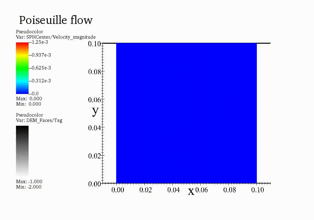
MechSys uses VisIt to visualise simulation results. A full tutorial can be found here. After following the instructions and choosing a Pseudocolor->SPHCenter->Velocity_magnitude data type to be visualised, the dynamics of the system should resemble the following video:
Publications
- Korzani, M. G., Galindo Torres, S., Scheuermann, A., & Williams, D. J. (2016). Smoothed particle hydrodynamics into the fluid dynamics of classical problems. In Applied Mechanics and Materials (Vol. 846, pp. 73-78). Trans Tech Publications Ltd.
- Korzani, M. G., Galindo-Torres, S. A., Scheuermann, A., & Williams, D. J. (2017). Parametric study on smoothed particle hydrodynamics for accurate determination of drag coefficient for a circular cylinder. Water Science and Engineering, 10(2), 143-153.
- Korzani, M. G., Galindo-Torres, S. A., Scheuermann, A., & Williams, D. J. (2018). Smoothed Particle Hydrodynamics for investigating hydraulic and mechanical behaviour of an embankment under the action of flooding and overburden loads. Computers and Geotechnics, 94, 31-45.
- Korzani, M. G., Galindo-Torres, S. A., Scheuermann, A., & Williams, D. J. (2018). SPH approach for simulating hydro-mechanical processes with large deformations and variable permeabilities. Acta Geotechnica, 13(2), 303-316.
- Trujillo-Vela, M. G., Galindo-Torres, S. A., Zhang, X., Ramos-Cañón, A. M., & Escobar-Vargas, J. A. (2020). Smooth particle hydrodynamics and discrete element method coupling scheme for the simulation of debris flows. Computers and Geotechnics, 125, 103669.
References
- Braune, L. & Lewiner, T. (2013). An initiation to sph. Rio de Janeiro: PUC-Rio, pages 1–7.
- Bui, H. H., & Nguyen, G. D. Smoothed particle hydrodynamics (SPH) and its applications in geomechanics. ALERT Doctoral School 2020 Point-based numerical methods in geomechanics, 3.
- Bui, H. H., Fukagawa, R., Sako, K., & Ohno, S. (2008). Lagrangian meshfree particles method (SPH) for large deformation and failure flows of geomaterial using elastic-plastic soil constitutive model. International journal for numerical and analytical methods in geomechanics, 32(12), 1537-1570.
- Cole, R. H., & Weller, R. (1948). Underwater explosions. PhT, 1(6), 35.
- Dehnen, W., & Aly, H. (2012). Improving convergence in smoothed particle hydrodynamics simulations without pairing instability. Monthly Notices of the Royal Astronomical Society, 425(2), 1068-1082.
- Ghadimi, P., Farsi, M., and Dashtimanesh, A. (2012). Study of various numerical aspects of 3d-sph for simulation of the dam break problem. Journal of the Brazilian Society of Mechanical Sciences and Engineering, 34(4):486–491.
- Gray, J. P., Monaghan, J. J., & Swift, R. P. (2001). SPH elastic dynamics. Computer methods in applied mechanics and engineering, 190(49-50), 6641-6662.
- Ké, D. D., & Turcotte, G. (1980). Viscosity of biomaterials. Chemical Engineering Communications, 6(4-5), 273-282.
- Monaghan, J. J. (2000). Sph without a tensile instability. Journal of Computational Physics, 159(2):290–311.
- Monaghan, J. J. (2005). Smoothed particle hydrodynamics. Reports on progress in physics, 68(8):1703–1759.
- Morris, J. P., Fox, P. J., & Zhu, Y. (1997). Modeling low Reynolds number incompressible flows using SPH. Journal of computational physics, 136(1), 214-226.
- Morris, J. P. (2000). Simulating surface tension with smoothed particle hydrodynamics. International journal for numerical methods in fluids, 33(3), 333-353.
- Imran, J., Parker, G., Locat, J., & Lee, H. (2001). 1D numerical model of muddy subaqueous and subaerial debris flows. Journal of hydraulic engineering, 127(11), 959-968.
- Papanastasiou, T. C. (1987). Flows of materials with yield. Journal of Rheology, 31(5), 385-404.
- Peng, C., Wu, W., Yu, H. S., & Wang, C. (2015). A SPH approach for large deformation analysis with hypoplastic constitutive model. Acta Geotechnica, 10(6), 703-717.
- Shao, S., & Lo, E. Y. (2003). Incompressible SPH method for simulating Newtonian and non-Newtonian flows with a free surface. Advances in water resources, 26(7), 787-800.
- Takeda, H., Miyama, S. M., & Sekiya, M. (1994). Numerical simulation of viscous flow by smoothed particle hydrodynamics. Progress of theoretical physics, 92(5), 939-960.